I was playing SimCity and this conversation started in my head:
Me one: How hard is it to build an Arduino-based relay controller around the house?
Me two: Yeah… How hard is it? One Arduino to rule them all?
Me one: Naaaa, too many I/O ends to be handled by a single Arduino. How about a bunch of Arduinos? One in each location handling both sensors and switches?
Me two: Alright, we’ll take it from there. What about communication?
Me one: Wireless; XBEE or WiFi shield
Me two: Good, but I’ve got better. Ethernet shield?
Me one: As far as I know, Ethernet shield takes many I/O ports
Me two: No I googled, it only takes, like, 4 I/O ports!
Me one: Urgh. Now I have to know how to handle network settings and stuff… But totally worth it.
In case you’re wondering, yes. I do talk to myself in many cases to resolve or think. Why? I don’t know how or why to explain. It just works.
Anyway, so I googled around on how to code for an Ethernet shield and, to my surprise, it’s almost as easy as writing a “Hello, world!” application on Windows Phone (To me, it’s almost impossible for me to do it in iOS. Took me days to figure that out!).
OK, let me explain what the final project should be:
* A set of Arduinos with Ethernet shield scattered around the house connected to a switch (Or hub). Each Arduino will be called “Node”.
* Each Node will have the ability install few sensors (Sound, IR, Sonicwave, Light) and\or AC relay switches.
* Each Node sends readings and receive commands through UDP or TCP (Depends on future progress) connections sent through Ethernet.
* A centralized computer with a server application to monitor and control them all.
I decided to go Arduino with Ethernet shield a location because having long small wires for many sensors and witch controllers isn’t wise. That, and the fact there’s a PoE Ethernet shield. That means I can just plug it to an Ethernet cable and not worry about power outage and someone accidentally turning the Node off.
I also decided to go with centralized computer to act as a server instead of having each nodes connected to is because, well, it’s easier and you can actually push updates to nodes whenever you update commands for example. That, and you’d know if a Node is having an issue if the TCP connection dropped for example.
I’m still confused on whether or not I should use UDP or TCP connection. But most likely will end up with TCP.
Now, first day I wanted to know how to send UDP packets through Arduino and Ethernet shield. Here’s how it looks like:
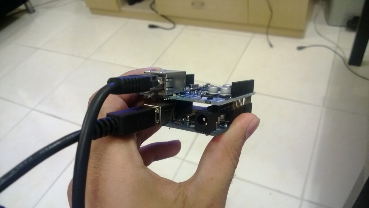
Yes, I thought I’d need to have to plug more stuff. I didn’t.
And to make it weirder (At least for me since plain easy stuff doesn’t make sense to me and I consider them hard and weird *COUGH*JAVA*COUGH*JAVA), here’s the example code on how to send a UDP packet:
#include

#include

#include
byte mac[] = { 0xDE, 0xAD, 0xBE, 0xEF, 0xFE, 0xED };
IPAddress ip(192, 168, 1, 221);
IPAddress server(192, 168, 1, 11a1);
unsigned int localport = 8888;
unsigned int remoteport = 8008;
char message[] = "ICANHASCHEEZBURGER!?";
EthernetUDP udp;
void setup() {
Ethernet.begin(mac,ip);
udp.begin(localport);
Serial.begin(9600);
}
void loop() {
udp.beginPacket(server, remoteport);
udp.write(message);
udp.endPacket();
delay(3000);
}
Explaining the code above in steps:
1. Include SPI.h, Ethernet.h, EthernetUDP.h
2. Set up Mac address (Used 0xDEADBEEFFEED as a Mac address. This is usually used by Arduino forum and examples… Funny, isn’t it?)
3. Set up your, server’s IP Addresses, message to be sent.
4. Set a udp socket and start it up.
5. Loop, send, and wait for 3 seconds before you send the next message.
Here’s a Wireshark dump to show what I received (I’m proud):

Next update will include a a sensor and sending readings through Ethernet. So stay tuned 😀
2 thoughts on “My first serious Arduino project: Ethernet Relay Controller – Day 1”